26+ system level block diagram
Get the paper and pencil and start the work. Japan 10-15 mode is used for the calculation.

Past Programs Economic Growth Institute
This section explains the Top Level Block Diagram of the LinuxGNU CAD CAM project.
. I would like to emphasize that there are very few assumptions made at this level of design. It was created in ConceptDraw DIAGRAM diagramming and vector drawing software using the Block Diagrams Solution from the Diagrams area of ConceptDraw Solution Park. This block diagram shows all of the.
The RXT system made for this evaluation is composed of a pure BEV and a trailer with an electric generator. Summing and Take-off Point. Up to 24 cash back Drawing by hands.
High-Level Block Diagram Versal ACAP Technical Reference Manual AM011 Document ID AM011 Release Date 2022-04-26 Revision 14. The design process begins independent of the hardware architecture or the operating system. Functional Software Electrical etc.
Block Diagrams Blocks with Perspective Callouts Connectors Raised Blocks from the solution Block Diagrams contain specific block diagram symbols such. The Top Level Block Diagram does not look very. Block Diagrams IntroductionTopics discussed1.
The result shows that 354 kWhweeks is. The inputs from the formula car and the user are sent to the. H ARDWARE D ESIGN A system-level diagram of the neural biotelemetry system is depicted in Figure 1.
A block diagram is a specialized flowchart typically used by engineers to provide a visualization of systems and their various interactions. Elements of a Block Diagram3. The vector stencils libraries.
Make three boxes inside the main. Ad Templates Tools To Make Block Diagrams. The TelosB mote-based communication system.
Its structure provides a high-level overview. A system level block diagram for the project entitled Microcontroller Driven Electroluminescent Display is shown in Figure 1. Figure 1 Hardware System Level Block Diagram Each hardware subsystem can be seen in the Hardware System Level Block Diagram above in Figure 1.
The system can be divided into two major sub-systems. First draw the large and broad rectangle in the vertical form. A block diagram is a specialized high-level flowchart used in engineering.
Top Level Block Diagram. It is used to design new systems or to describe and improve existing ones. Introduction of Block Diagrams2.
Block diagrams are ideal for creating a high-level. USB Controller Block Diagram.
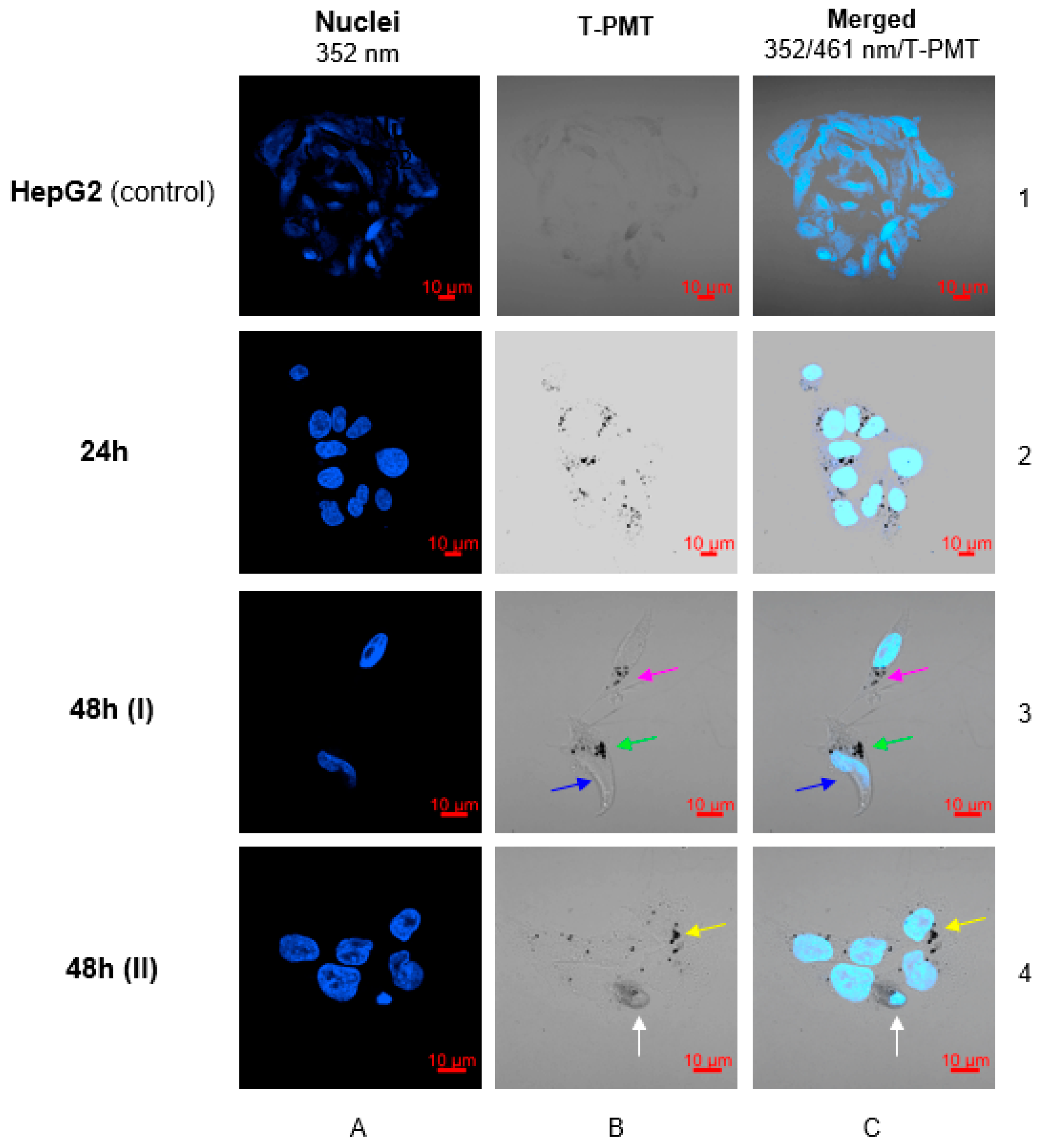
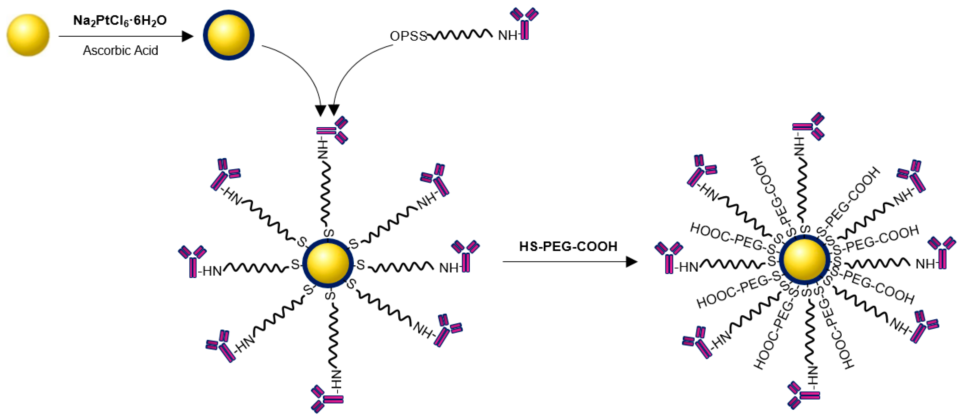
Molecules Free Full Text Au Pt Core Shell Nanoparticle Bioconjugates For The Therapy Of Her2 Breast Cancer And Hepatocellular Carcinoma Model Studies On The Applicability Of 193mpt And 195mpt Radionuclides In Auger Electron

Type 26 Global Combat Ship Capabilities Think Defence
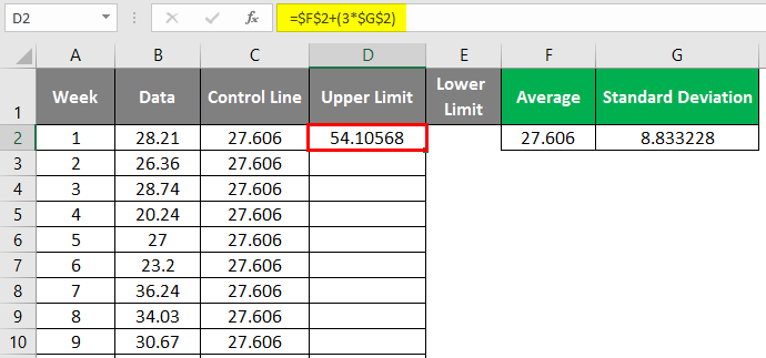
Control Charts In Excel How To Create Control Charts In Excel

V8uixo5ysbfx6m
2
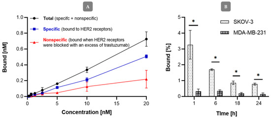
Molecules Free Full Text Au Pt Core Shell Nanoparticle Bioconjugates For The Therapy Of Her2 Breast Cancer And Hepatocellular Carcinoma Model Studies On The Applicability Of 193mpt And 195mpt Radionuclides In Auger Electron
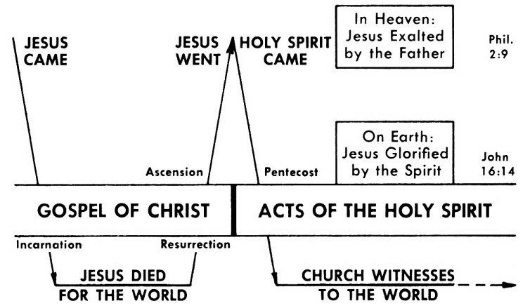
Acts 26 Commentary Precept Austin
A Beginners Guide To Covalent Covalent
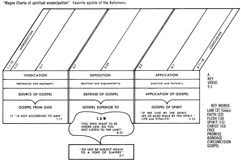
Galatians 5 Commentary Precept Austin
2
Molecules Free Full Text Au Pt Core Shell Nanoparticle Bioconjugates For The Therapy Of Her2 Breast Cancer And Hepatocellular Carcinoma Model Studies On The Applicability Of 193mpt And 195mpt Radionuclides In Auger Electron
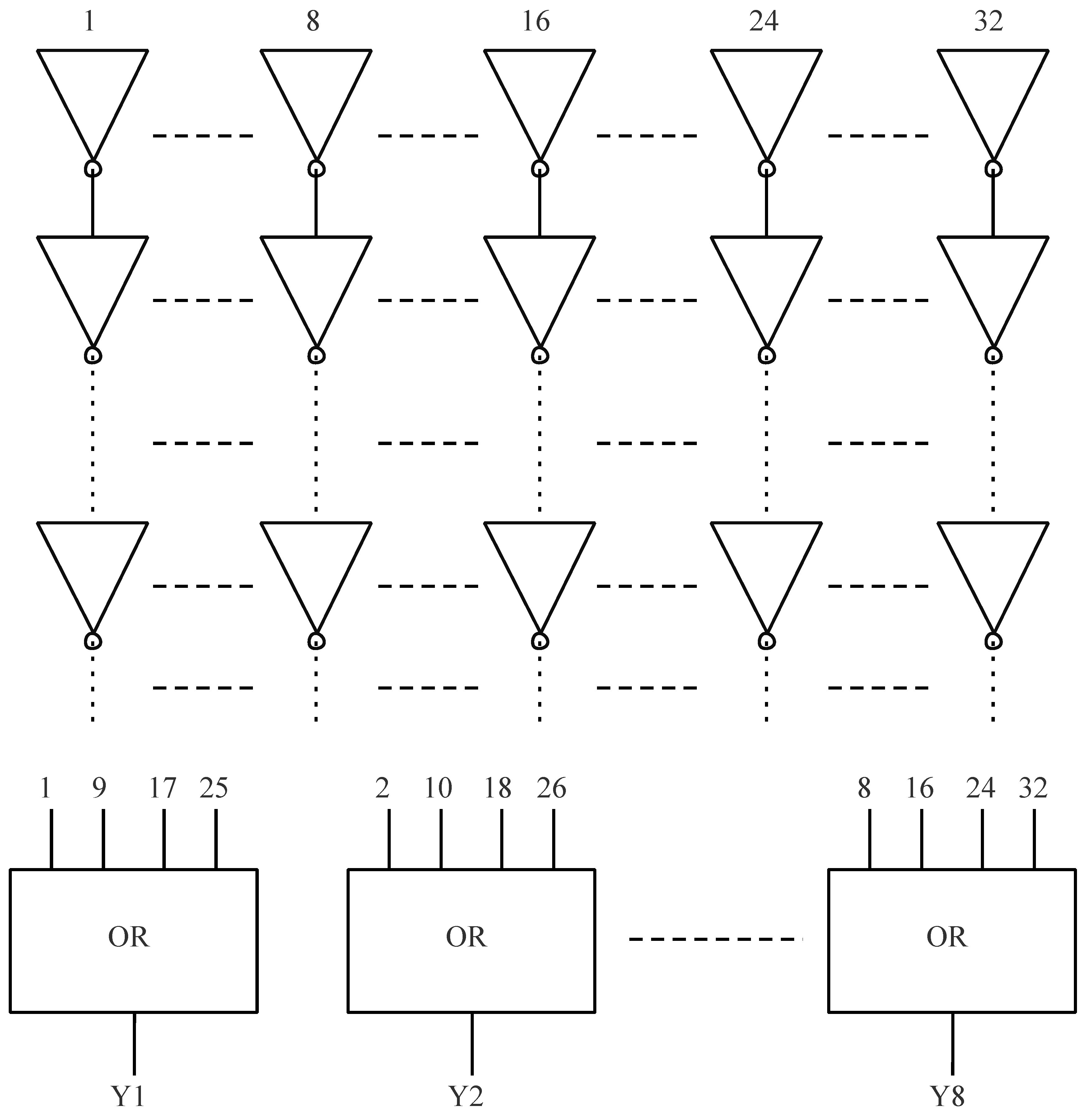
Symmetry Free Full Text Investigation Of Heavy Ion Induced Single Event Transient In 28 Nm Bulk Inverter Chain Html
2

Molecules Free Full Text Au Pt Core Shell Nanoparticle Bioconjugates For The Therapy Of Her2 Breast Cancer And Hepatocellular Carcinoma Model Studies On The Applicability Of 193mpt And 195mpt Radionuclides In Auger Electron
Acts 26 Commentary Precept Austin

Fabrication Of Double Conical Pet Nanochannel For Molecular Detection Sciencedirect
2